Nanofader PT01 Install Guide
Contents
Step 1 - Open the PT-01
Remove all of the screws from the bottom of the PT-01, and lift the top section off. Unplug the black ribbon cable linking the top and bottom sections.
Unscrew the main board
The main board is located in the top section, and looks like this :
Unscrew the four screws holding it to the case, and flip it over so you can access the underside. You'll probably have to remove a lot of hot glue to get enough slack on the cables.
Remove C8 and C18
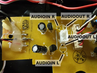
Locate capacitors C8 and C18, which are towards the top left of the board (in the above picture). Desolder and remove them, like so :
Replace C8 and C18 with wires
The capacitors need to be replaced with wires that connect to the nanofader board. The connections should be made as follows :
Use one cable for the AUDIO IN L/R connections, and another cable for the AUDIO OUT L/R connections, like so :
The ground should only be connected at the nanofader end.
You can now screw the main board back in.
Power Connection
Cut the useless USB cable down to about a half inch


