Difference between revisions of "Nanofader PT01 Install Guide"
(→FADER) |
|||
| Line 5: | Line 5: | ||
===Board placement=== | ===Board placement=== | ||
| − | Probably the best place for the nanofader board is next to the power supply board : | + | Probably the best place for the nanofader board is next to the power supply board : |
| + | |||
| + | [[File:Pt01mod-placement.jpg|400px]] | ||
Don't secure the board to the pt-01 case until you have connected and tested everything. | Don't secure the board to the pt-01 case until you have connected and tested everything. | ||
| + | |||
===Unscrew the main board=== | ===Unscrew the main board=== | ||
| Line 16: | Line 19: | ||
Unscrew the four screws holding it to the case, and flip it over so you can access the underside. You'll probably have to remove a lot of hot glue to get enough slack on the cables. | Unscrew the four screws holding it to the case, and flip it over so you can access the underside. You'll probably have to remove a lot of hot glue to get enough slack on the cables. | ||
| + | |||
===Remove C8 and C18=== | ===Remove C8 and C18=== | ||
| Line 22: | Line 26: | ||
[[File:Pt01mod-removed_caps.jpg|400px]] | [[File:Pt01mod-removed_caps.jpg|400px]] | ||
| + | |||
===Replace C8 and C18 with wires=== | ===Replace C8 and C18 with wires=== | ||
| Line 36: | Line 41: | ||
You can now screw the main board back in. | You can now screw the main board back in. | ||
| + | |||
===Power Connection=== | ===Power Connection=== | ||
| Line 43: | Line 49: | ||
[[File:Pt01mod-power_connector.jpg|400px]] | [[File:Pt01mod-power_connector.jpg|400px]] | ||
| − | Cut the USB power cable down to about 10cm or so and strip the ends. | + | Cut the USB power cable down to about 10cm or so and strip the ends : |
| + | |||
| + | [[File:Pt01mod-power_wire.jpg|400px]] | ||
| + | |||
===AUX IN connection=== | ===AUX IN connection=== | ||
| − | We can also hijack the USB board's AUX IN connector. The pinout of the connector is as follows : | + | We can also hijack the USB board's AUX IN connector. The pinout of the connector is as follows : |
| + | |||
| + | [[File:Pt01-aux_wiring.jpg|400px]] | ||
| + | |||
| + | Solder a longer length of audio cable to the underside of the USB board like so : | ||
| + | |||
| + | [[File:IMG_20160307_184058.jpg|400px]] | ||
| − | |||
===Nanofader connections=== | ===Nanofader connections=== | ||
| Line 56: | Line 70: | ||
All of the connections are made using green screw-in terminal blocks. To connect a wire, first strip the end (if necessary), make sure the terminal is completely unscrewed, then insert it into the terminal and turn the screw clockwise until it tightens. | All of the connections are made using green screw-in terminal blocks. To connect a wire, first strip the end (if necessary), make sure the terminal is completely unscrewed, then insert it into the terminal and turn the screw clockwise until it tightens. | ||
| + | |||
====POWERIN==== | ====POWERIN==== | ||
| Line 61: | Line 76: | ||
The power cable (originally from the USB board) connects to the POWERIN connector on the nanofader. The red wire connects to the "+" terminal, and the white connects to the "G" terminal. | The power cable (originally from the USB board) connects to the POWERIN connector on the nanofader. The red wire connects to the "+" terminal, and the white connects to the "G" terminal. | ||
| − | + | [[File:Pt01mod-power_connected.jpg|600px]] | |
| + | |||
====AUDIOIN and AUDIOOUT==== | ====AUDIOIN and AUDIOOUT==== | ||
| Line 68: | Line 84: | ||
(TODO - Pic of audio connector, just AUDIOIN will suffice) | (TODO - Pic of audio connector, just AUDIOIN will suffice) | ||
| + | |||
| + | [[File:Pt01mod-audioin_wiring.jpg|600px]] | ||
| + | |||
====AUX IN==== | ====AUX IN==== | ||
The AUX cable coming from the USB board should be connected just like the AUDIOIN and AUDIOOUT cables. | The AUX cable coming from the USB board should be connected just like the AUDIOIN and AUDIOOUT cables. | ||
| + | |||
====FADER==== | ====FADER==== | ||
| Line 78: | Line 98: | ||
[[Nanofader_Fader_Guide|Click here]] for a full guide on how to connect various different fader types to the nanofader, including mounting suggestions. | [[Nanofader_Fader_Guide|Click here]] for a full guide on how to connect various different fader types to the nanofader, including mounting suggestions. | ||
| + | |||
===POWER ON=== | ===POWER ON=== | ||
| Line 84: | Line 105: | ||
If the cut-in distance is too large, or the fader doesn't cut the sound, go to the next section. | If the cut-in distance is too large, or the fader doesn't cut the sound, go to the next section. | ||
| + | |||
===Adjust Lag (optional)=== | ===Adjust Lag (optional)=== | ||
With the fader closed, adjust the LAG pot with a small flathead screwdriver, until it JUST cuts the sound out and no more. Doing this with a record playing might be fiddly, maybe find something to stand the top section of the PT-01 on while you adjust the pot. (TODO - Pic of lag adjust) | With the fader closed, adjust the LAG pot with a small flathead screwdriver, until it JUST cuts the sound out and no more. Doing this with a record playing might be fiddly, maybe find something to stand the top section of the PT-01 on while you adjust the pot. (TODO - Pic of lag adjust) | ||
Revision as of 18:21, 7 March 2016
Contents
Open the PT-01
Remove all of the screws from the bottom of the PT-01, and lift the top section off. Unplug the black ribbon cable linking the top and bottom sections.
Board placement
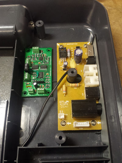
Probably the best place for the nanofader board is next to the power supply board :
Don't secure the board to the pt-01 case until you have connected and tested everything.
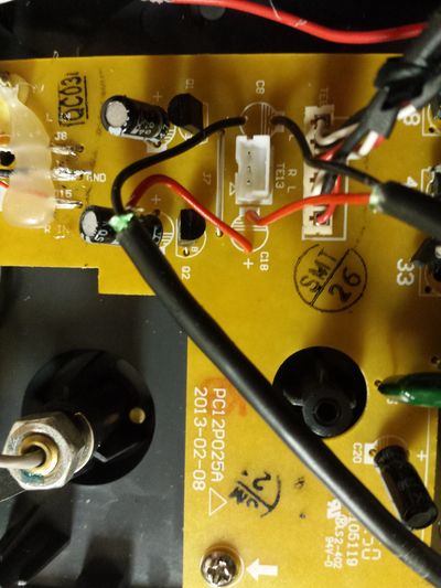
Unscrew the main board
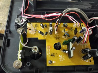
The main board is located in the top section, and looks like this :
Unscrew the four screws holding it to the case, and flip it over so you can access the underside. You'll probably have to remove a lot of hot glue to get enough slack on the cables.
Remove C8 and C18
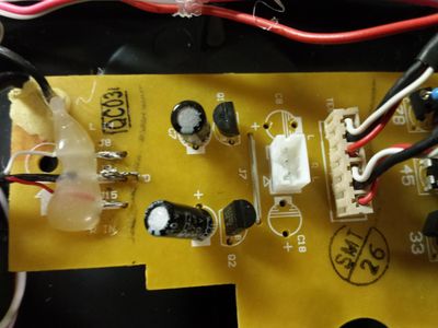
Locate capacitors C8 and C18, which are towards the top left of the board (in the above picture). Desolder and remove them, like so :
Replace C8 and C18 with wires
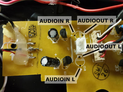
The capacitors need to be replaced with wires that connect to the nanofader board. The connections should be made as follows :
Use one short cable for the AUDIO IN L/R connections, and another short cable for the AUDIO OUT L/R connections, like so :
The ground should only be connected at the nanofader end.
You can now screw the main board back in.
Power Connection
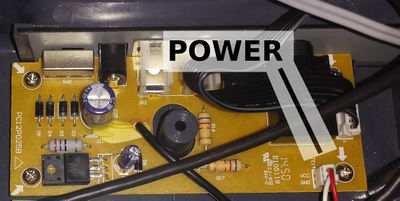
The power PCB is found in the lower section of the pt-01. We are going to disable the (pointless) USB board and steal its power connection :
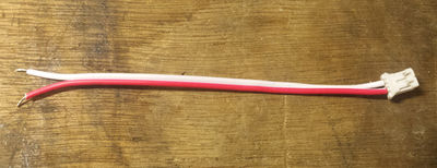
Cut the USB power cable down to about 10cm or so and strip the ends :
AUX IN connection
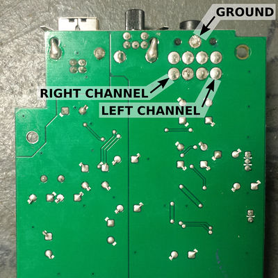
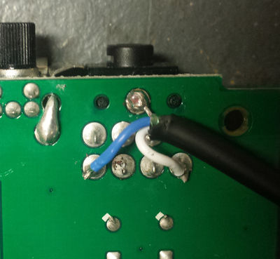
We can also hijack the USB board's AUX IN connector. The pinout of the connector is as follows :
Solder a longer length of audio cable to the underside of the USB board like so :
Nanofader connections
Now it's time to connect everything to the nanofader board!
All of the connections are made using green screw-in terminal blocks. To connect a wire, first strip the end (if necessary), make sure the terminal is completely unscrewed, then insert it into the terminal and turn the screw clockwise until it tightens.
POWERIN
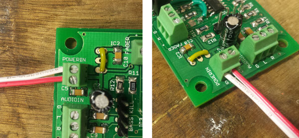
The power cable (originally from the USB board) connects to the POWERIN connector on the nanofader. The red wire connects to the "+" terminal, and the white connects to the "G" terminal.
AUDIOIN and AUDIOOUT
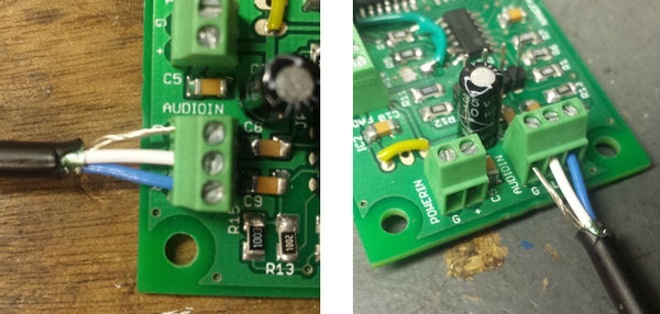
The wires that replaced C8 and C18 are connected to the AUDIOIN and AUDIOOUT connectors. The shield of the cables should be connected to the "G" connector, and the left and right wires go to "L" and "R" respectively.
(TODO - Pic of audio connector, just AUDIOIN will suffice)
AUX IN
The AUX cable coming from the USB board should be connected just like the AUDIOIN and AUDIOOUT cables.
FADER
If you got your fader from me, I'll have labelled the wires. Connect "WWWWW" or "WIPER" to the "W" terminal of the FADER connector, and "GND" to the "G" terminal.
Click here for a full guide on how to connect various different fader types to the nanofader, including mounting suggestions.
POWER ON
Power on the PT-01, start a record playing and check nothing blows up. Make sure the fader cuts the sound in and out (check both sides), and that the AUX IN works.
If the cut-in distance is too large, or the fader doesn't cut the sound, go to the next section.
Adjust Lag (optional)
With the fader closed, adjust the LAG pot with a small flathead screwdriver, until it JUST cuts the sound out and no more. Doing this with a record playing might be fiddly, maybe find something to stand the top section of the PT-01 on while you adjust the pot. (TODO - Pic of lag adjust)
